cornfield customs
Well-known member
yea it will have drums all the way around. building this one very traditional

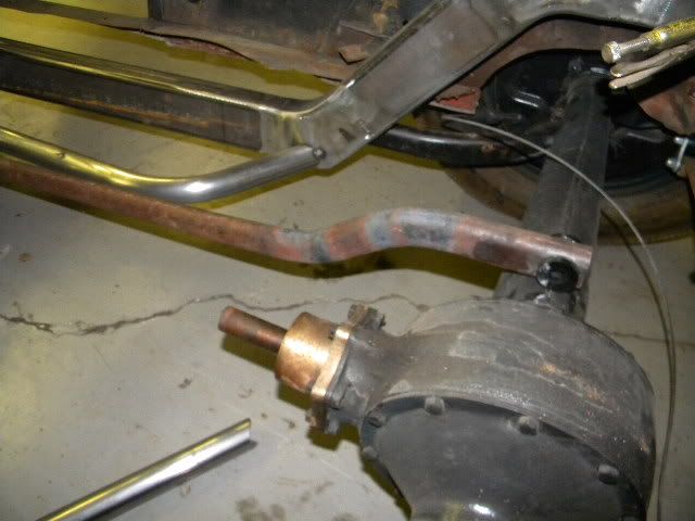
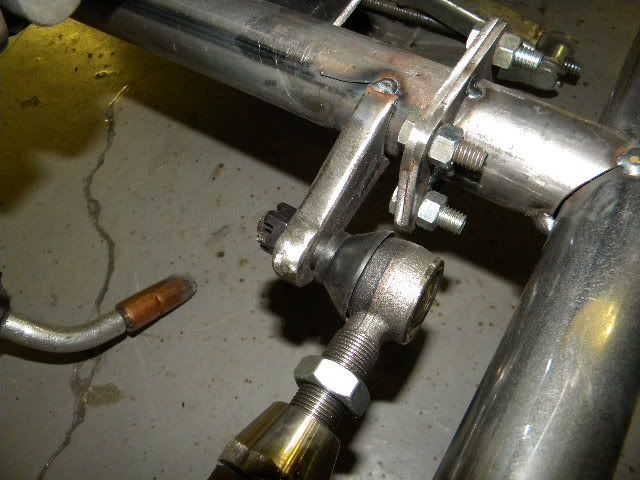
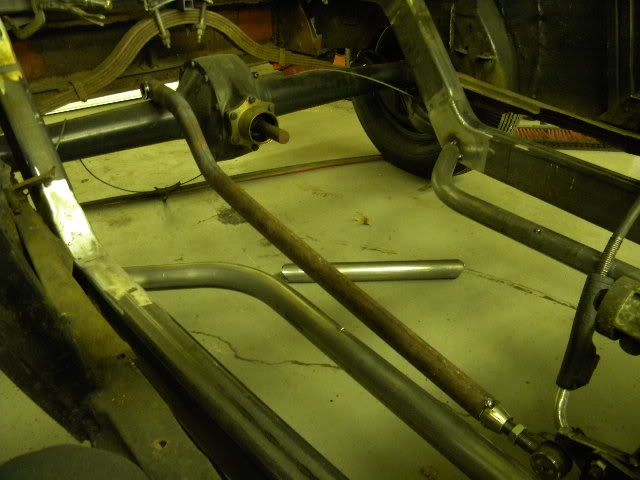
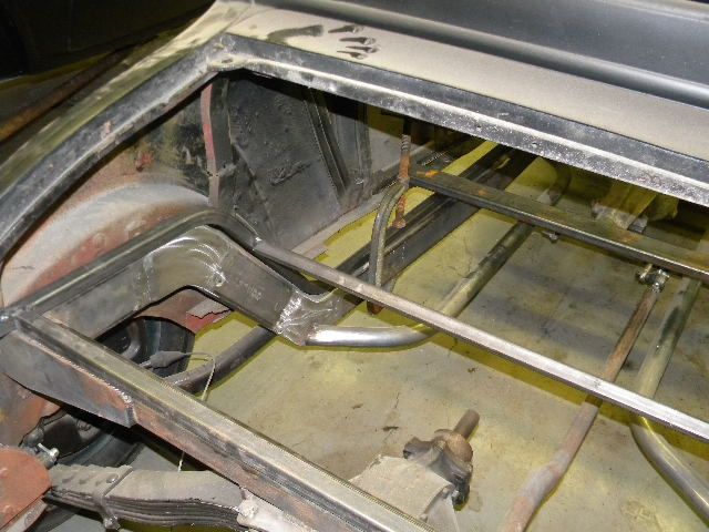
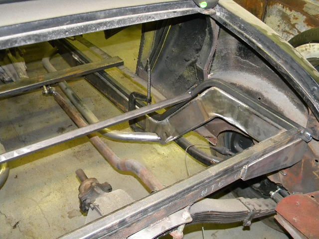
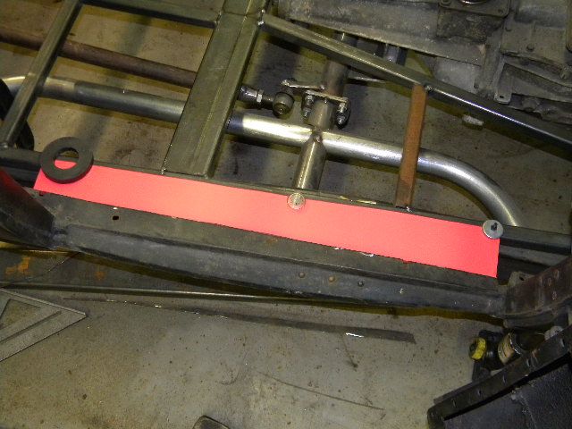
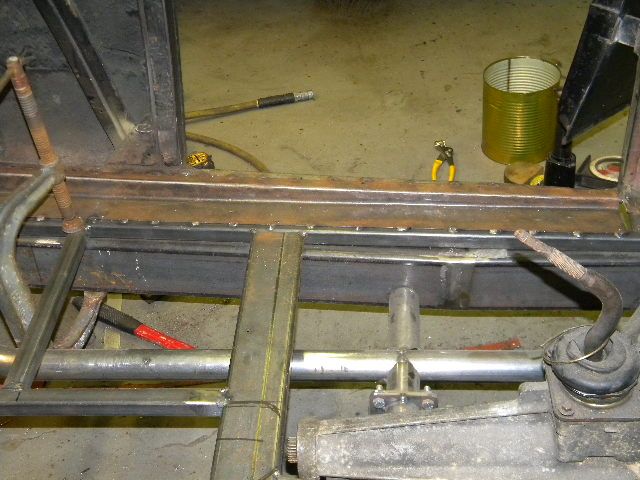
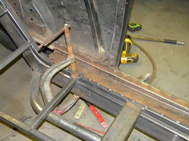
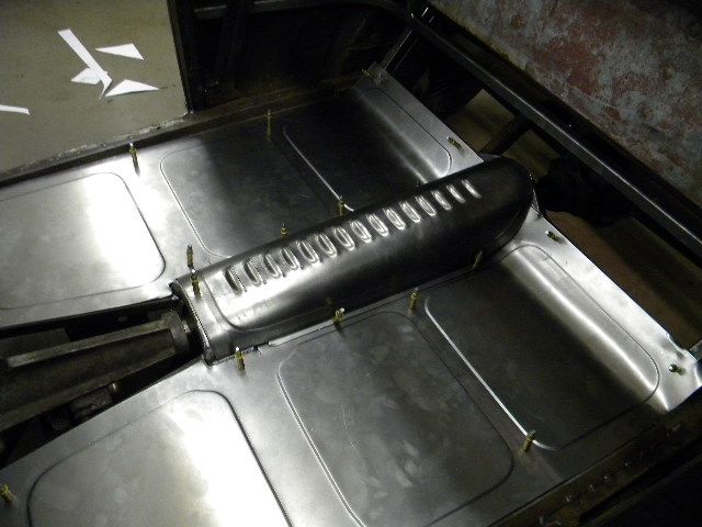
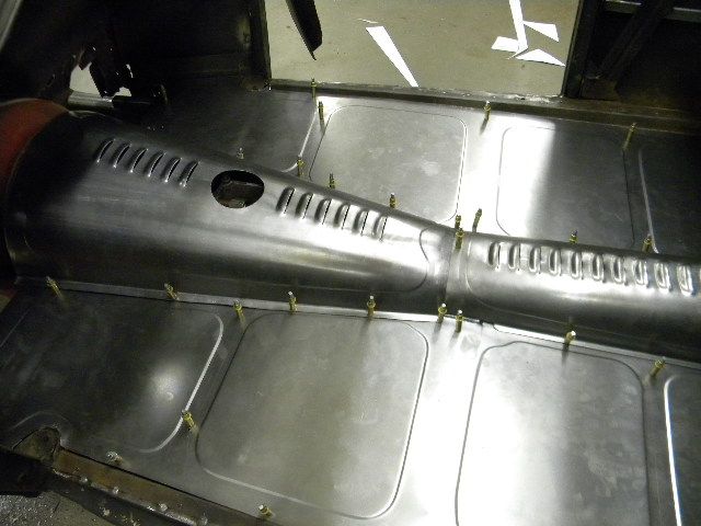
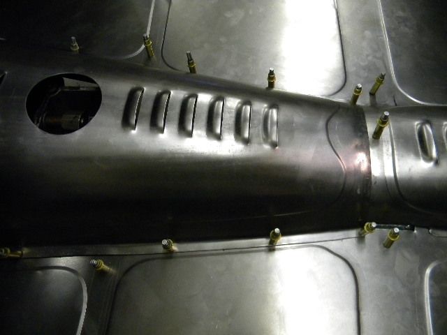
front mount of the torque arm, tie rod end, mount has the 7* taper reamed into it
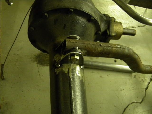
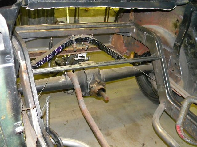
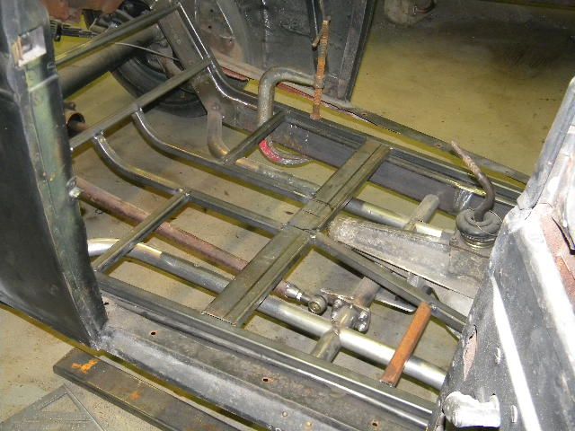
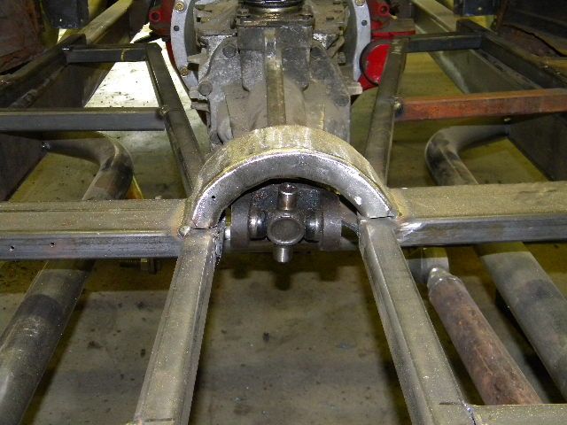
I was just wondering if you were going to add a second mount on the bottom side of the axle for your torque arm? With it only being attached at the top of the axle won't it still allow the axle to twist?

Enter your email address to join: