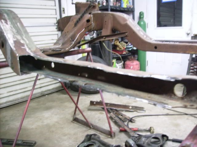
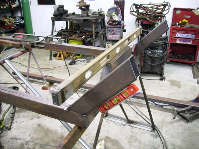
I got some more done on the frame after a a nights rest. First I notched the frame rail. I was goning to use the plasma cutter but it crapped out so I used the cut off wheel instead. Takes longer but better results.
I then cut 2 peices of 2x3 70" long with a 45 degree on the end.
Afterward I cut the cross member at the kick up 37" with 45's on each end then tacked it in place.
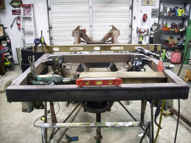
I'm about 1/4" out of square and I will work on that later. Still I'm pleased with the results so far. Sorry for the blurry pics. my camera really sucks.
That truck is going to sit so low ,I did that same set-up but with my rear rails on top of the sub frame and my running boards drug the ground . If you are not doing the running boards it's gonna be lookin good !
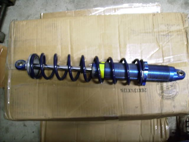
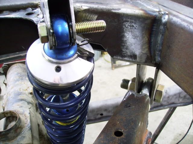
Not planning on running boards but you never know. I got one of my shocks today the other is on the way. They are aluminum body Afco 7" they came off of a freinds Late Model dirt car.
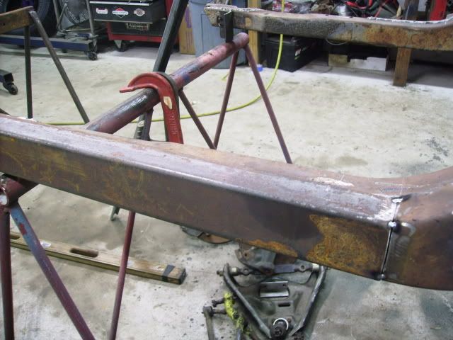
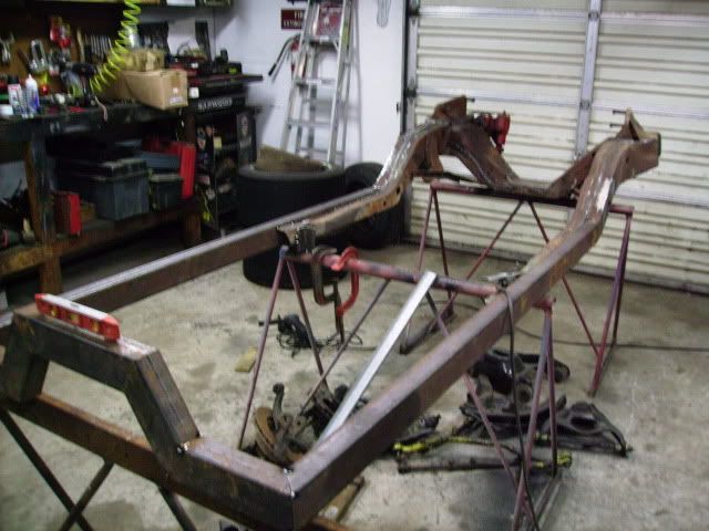
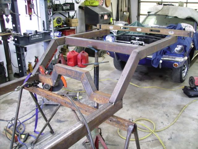
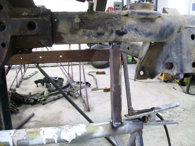
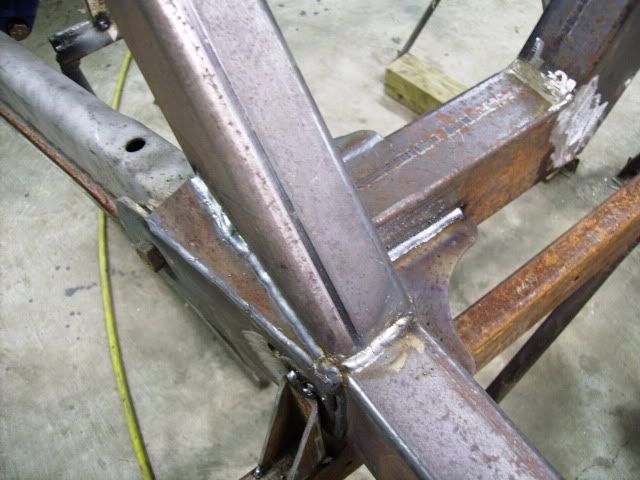
I also got some more done on the frame. Started the kick ups. 45 degree then 22.5 degree. I'll go back 36" from there. I still will need to determine where the next cross member will go. This is where the coil overs and upper controll arms will attach.
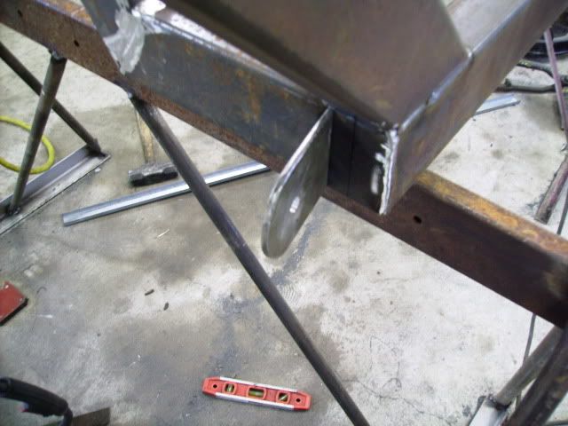
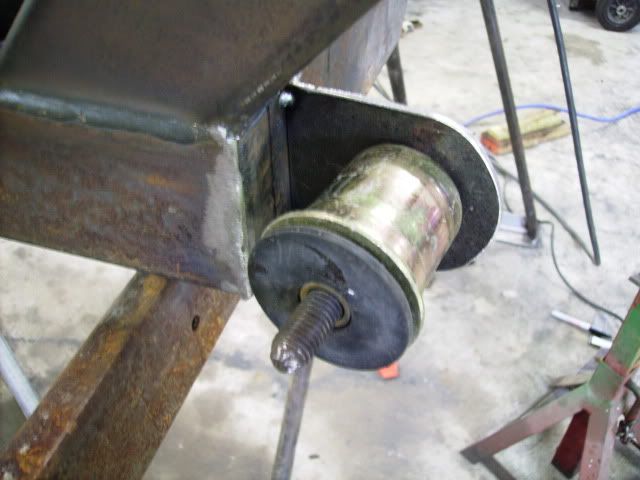
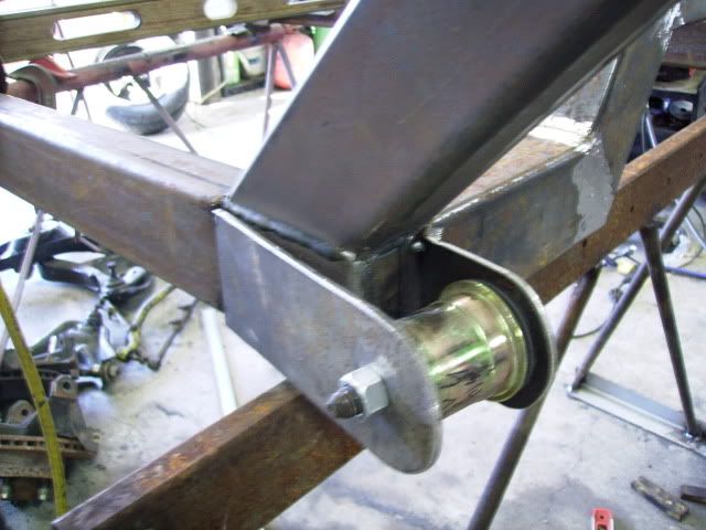
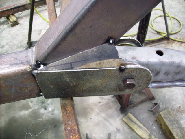
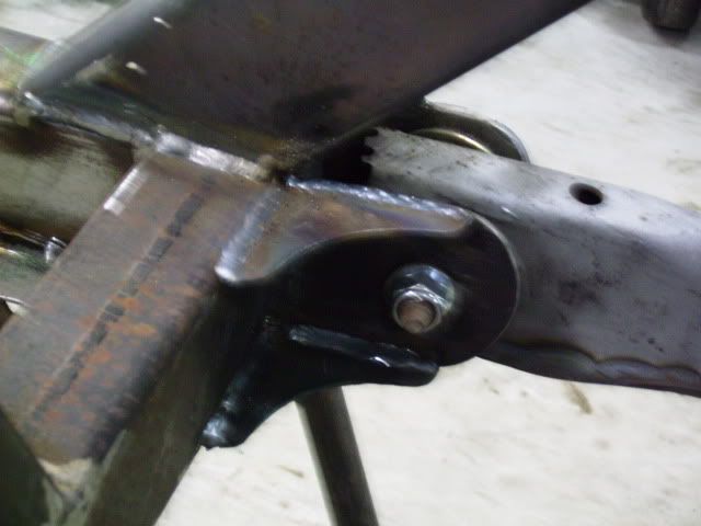
As I stated earlier I focused on the lower controll arm mounts. After checking and measuring several times I came to the conclusion that the lower arms are at 10 degree from 90. The top are at 45 Degrees. From the inside hole to the other side I came up with 34 1/4". I started by tacking the inside tab in place.
Then using a new polyuethane bushing that I had lying around I determined the location for the outside tab.
I'll add some gussets here later after I get it all sorted out and I am certain what I want.
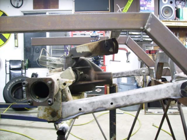
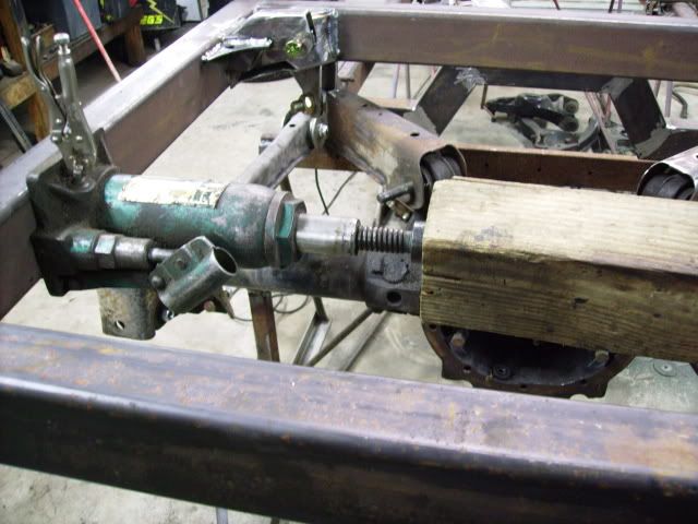
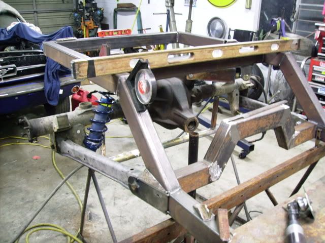
I agonized about this for a while but it was pretty easy and went well. For the next thing I placed a housing I already had taken apart on a work stand in it's approx. place. Wish I had both axles to this one as it in a not c-clip rear end. The one I intend to use is a c-clip unit.
Next I'll work on boxing the controll arms and get them in place.
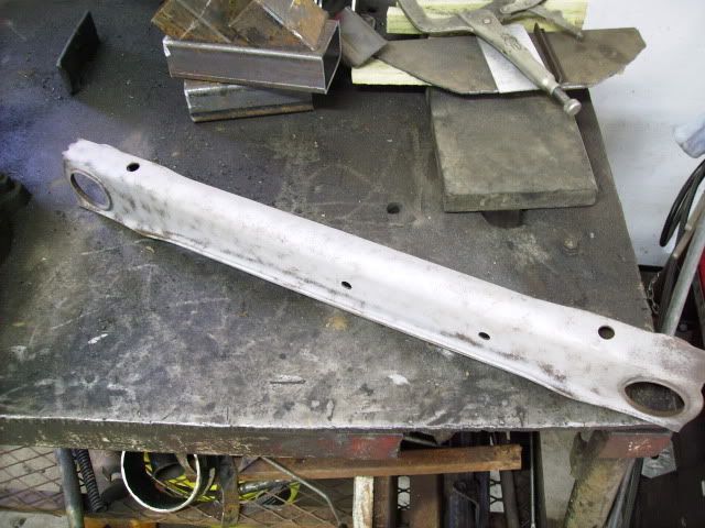
I worked on the lower controll arms today. After removing the bushings I bead blasted them.
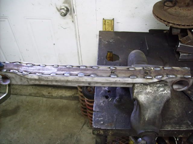
Then I cut some 24" x 1 3/8" strips from some 1/8" steel and tacked them into place after some hand forming on the open side of the contoll arm. After transfering 2 holes for the sway bar. I removed the strip and tacked 7/16 nuts to the back side. then stitch welded them back into place.
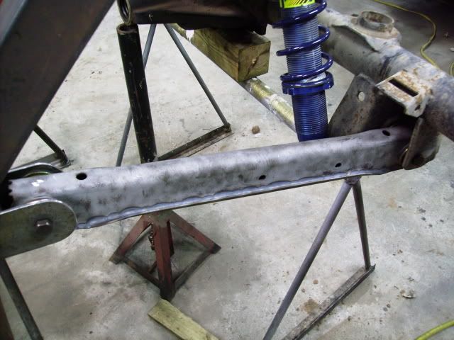
I then installed the poly bushings and put them in place.
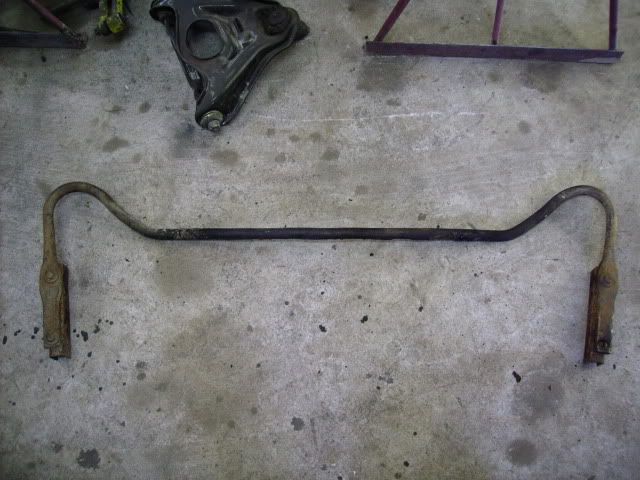
This is the sway bar I will use.
I'm now ready to work on the upper controll arms. I'm going to make them ajustable so I can change the pinion angle some.
I need to figure out what to use for upper bushings as I have only 4 poly ones and need 6. I might turn some out of aluminum. It will come to me.
Lookin' great Todd. Here's some really good info on rear suspension design/tuning that you might wanna digest before you nail down the location of your suspension mounts. It's aimed at drag race stuff but it still applies to about any rear wheel drive high performance vehicle. :
I'm not sure they are covering a typical coil spring set up on a a body GM car. For one the upper control arms are 1/2 the lenght as the lower 11 1/2" compared to 22" How does that affect instant center? I'm not sure. Another thing is that 4 links on a drag car seem to be in the same horizonal plane as compared to the 55 degree difference on a GM A body, I tried to glean some information on these on the net and mostly came up with nothing but sales pitches for control arms gizmos. What I can do is mimick the set up on my Oldsmoble which uses this exact same suspension. My biggest concern is the pinion angle. I checked the lower control arm angle on the Olds and they are 5 degrees upward at the front as the car set in a static posistion. I guess if it don't launch like Grumpy Jenkins Vega I'll just have to settle for what I have. Heck I'll be happy if it don't wheel hop like I've seen some of these cars do. If it will articulate through the lenght of travel without adversly affecting pinion angel I've done well. Still thanks for the input.
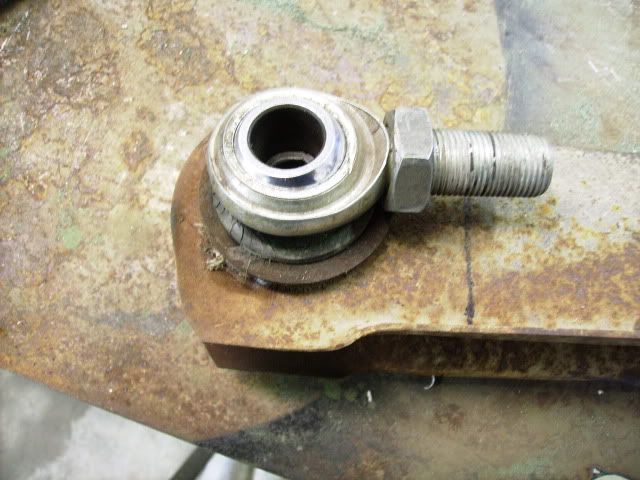
I been working on the upper controll arms. I decided I wanted to be able to adjust my pinion angle because I am not certain where the engine and trans will set exactly. This will give me some fudge room. With the short drive shaft I'll need it. Anyway I added 3/4" rod ends to the forward end of the upper arms. First I had to determine how much to shorten them so that they would still be about 11 1/4" in length.
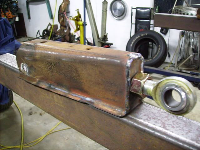
After cutting them 9" from the center of the rear bolt hole I added a 3/16" plate with a nut tacked inside to the end then boxed the bottom open with 1/8" steel.
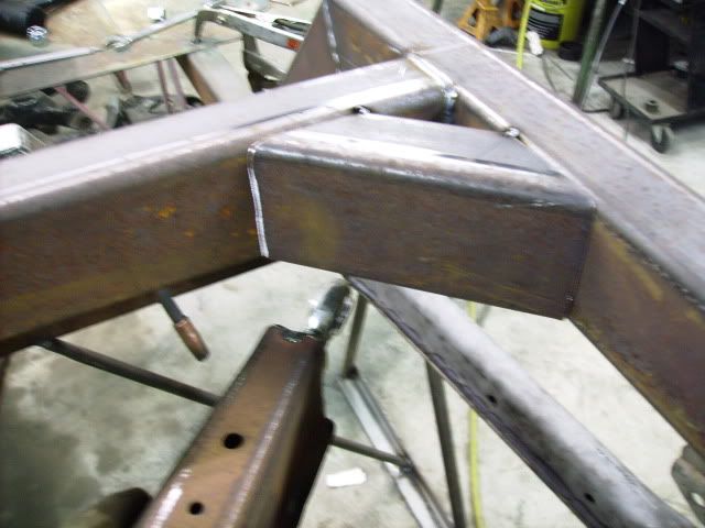
I decided to add some gussets to the cross member so that I will have a nice area to attach the tabs for the contoll arm mounts.
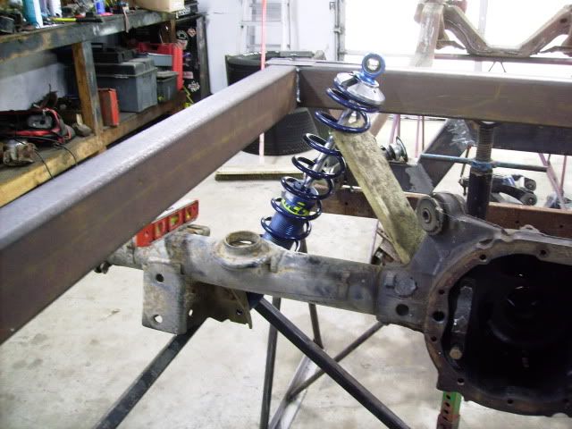
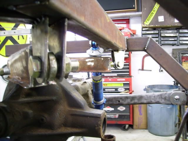
Another thing I did was make these stand things that attach to my saw horses to hold the rear end in it's theorectical place nice and level. This is where I hope the static ride height will end up. I might need to change springs or at very least adjust the preload on them.
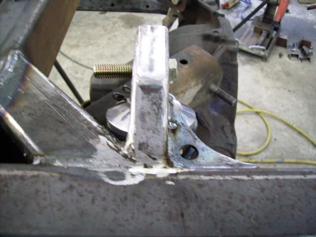
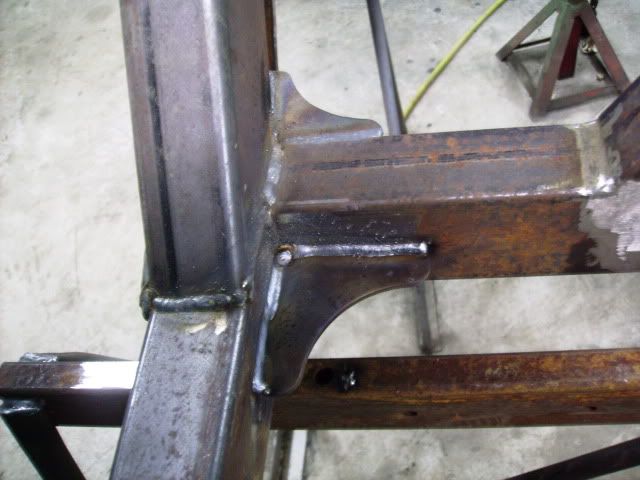
I moved on to getting the mounts built for the upper controll arms. I determined that they needed to be 2 5/8" from the frame. I made these mounts from some 3/16" steel.
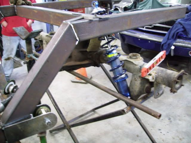
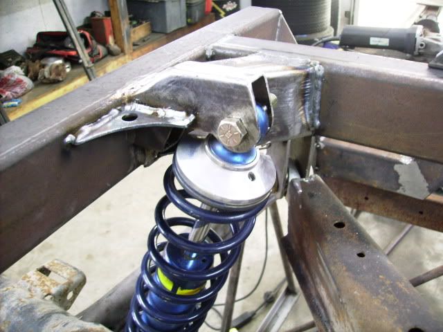
I'll finish up the welds when I flip it all. Afterwards I started the mounts for the coil overs. I used some 1x3" square tubing to make the mount. This took some time and some scratching of the head. I added the gusset brace for good measure. also I had to notch the corner brace some for clearance on the spring.
I moved the rearend through it's length of travel upward. Although I did not have any interference I think I'll chamfer the top of the upper controll arms just in case.
It won't be long and I'll move on to the engine and cab mounts.WEEEEEEE!
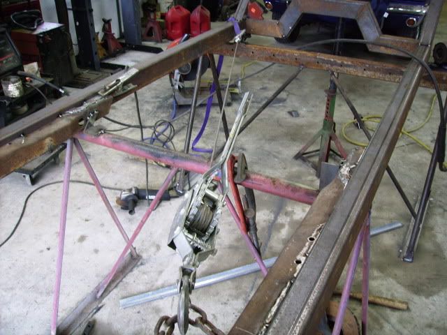
I had a little issue with the frame rails moving at the rear after I did the welding on the shock mounts. My solution was to spread it back out with a bottle jack and a 4x4 block. I added the rear cross member afterwords.
It's amazing how much this 2x3 steel will move when heated a little. before I added the rear cross member it was starting to get out of level also. I was glad to see spreading it back out brought it level again also.
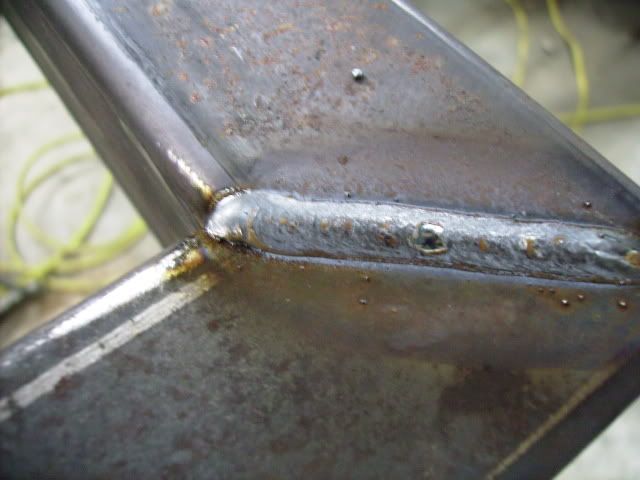
Sometimes my blind old and shakey butt can still scald some steel. not very often though.
I started working on some gussets for the lower contoll arms. Got a few more hours of that before I move on to the engine mounts.
The Sunflower swap meet is this weekend. maybe I'll find some treasure!
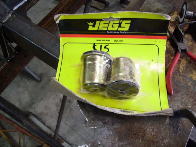
I picked up a few items at the local swap meet. I found 2 contoll arm bushings for 10 smackers. Now I won't need to turn some.
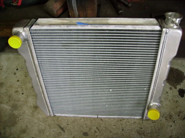
I also bought this new 22"x19" alum. radiator for a good price I could not turn down. $110 from 62ChevyII. He could not use it because of the way the lower outlet pointed. Looks like it will work for me. I'll add a trans. cooler and a good electric fan.
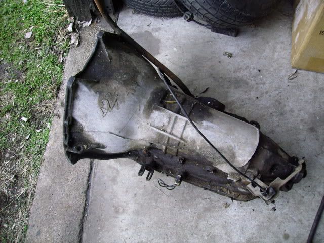
This is the 200R I decided to use. I have a 455 block and had some time to do a mock but the camera is acting up and won't focus under the lights so I'll try again when the sun gets up.
Hopefully I'll get the engine mounts fingered out this weekend. It should have about 12" set back from normal with plenty of room. I'll try to get some pics later.