dmw56
Busted and Rusted on Route 66
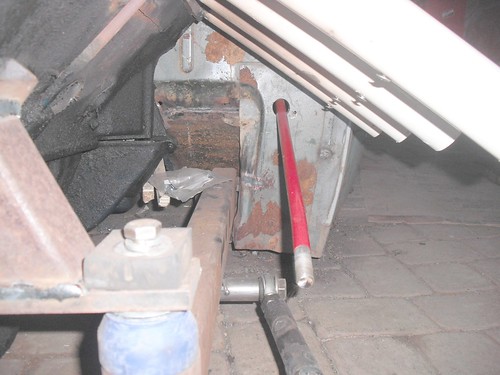
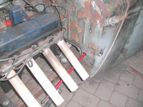
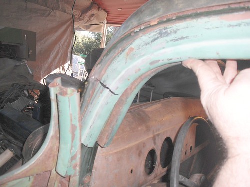
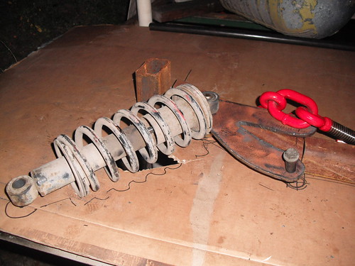
You may want to reinforce that front spring hanger with some gussets. It's supporting the weight of the whole front end.

 [
[
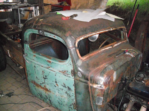
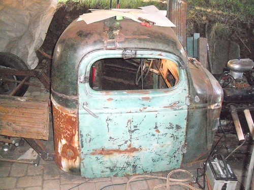
 ...on my 37 chevy.
Enter your email address to join: