kelseydum
Well-known member
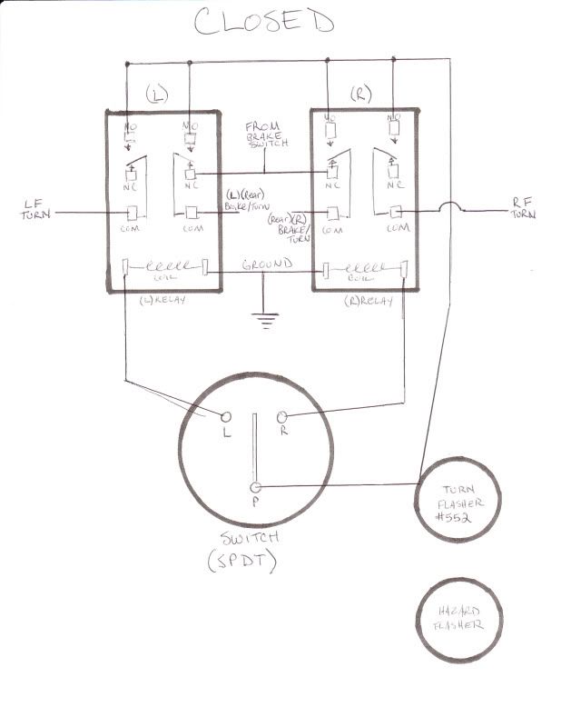
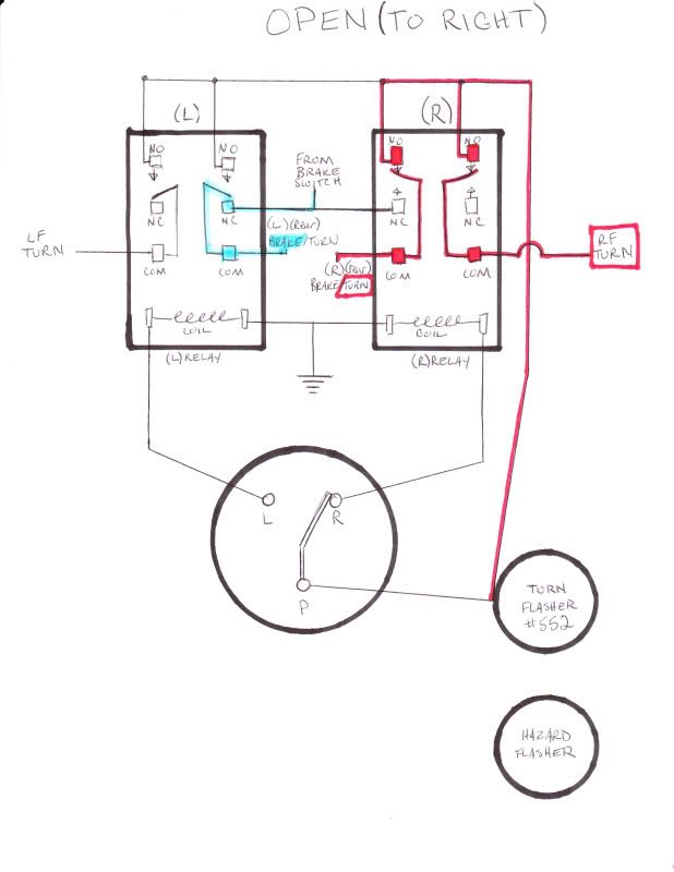
Is this legit? Does this seem like it would work? I'm trying to figure out a way to put my turn signals on a double pole/double throw switch and still have my brake switch work. I found this...
http://www.mg-tabc.org/techn-up/turn_signal_relay/turnsignalrelay.html
It seems cheap and should work. I need some electrician professional help.
http://www.mg-tabc.org/techn-up/turn_signal_relay/turnsignalrelay.html
It seems cheap and should work. I need some electrician professional help.