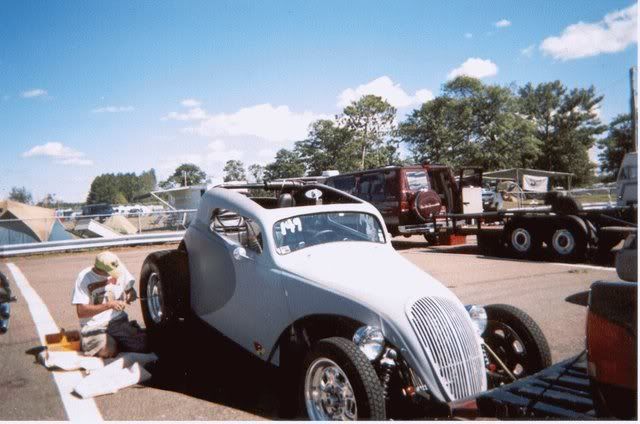
38 Fiat Topolino build

Rat Rods Rule

Help Support Rat Rods Rule:

This site may earn a commission from merchant affiliate links, including eBay, Amazon, and others.
Here's the seats mocked up in the car.
A little more work with the tape measure today and I realized that I could not close the doors when leaving enough room for the drive shaft to actually turn.:eek:

It does have to turn, doesn't it?:rolleyes:

So, I took one of the seat bottoms apart and have a plan to build a notch into the inner edge of both seats that will match the tunnel and that will mount the seats too. I love it when a plan comes together. I think I will shorten the seat cushion while I am at it and make the seats about 2" lower overall.

Tomorrow I can continue working on the rear links, still not sure what to do.
 

Attachments

  • Oct Fiat update 040.jpg
    Oct Fiat update 040.jpg
    85.8 KB · Views: 45
  • Oct Fiat update 042.jpg
    Oct Fiat update 042.jpg
    87.6 KB · Views: 34
  • Oct Fiat update 043.jpg
    Oct Fiat update 043.jpg
    81.8 KB · Views: 22
  • Oct Fiat update 045.jpg
    Oct Fiat update 045.jpg
    69.6 KB · Views: 31
  • Oct Fiat update 047.jpg
    Oct Fiat update 047.jpg
    98 KB · Views: 61
Here's the seats mocked up in the car.
A little more work with the tape measure today and I realized that I could not close the doors when leaving enough room for the drive shaft to actually turn.:eek:

.


I guess that is why alot of them just have one seat, right in the middle. :)
 
Your right Bonehead, but thats the easy way out.:rolleyes: I need something that I can scare my friends in.:eek:

Here are some updates.
Remodeled the passenger seat for the driveshaft. My shop neighbor does upholstry and is going to put it back on for me. Some slight modification at the bottom edge will be needed.:D The missing springs will be made up with some ridgid foam of the correct squishyness.

I am not going to finish till the drive shaft is in the car in case I need more room.
 

Attachments

  • seats and bars 001.jpg
    seats and bars 001.jpg
    73.4 KB · Views: 20
  • seats and bars 002.jpg
    seats and bars 002.jpg
    78.4 KB · Views: 18
  • seats and bars 005.jpg
    seats and bars 005.jpg
    132.1 KB · Views: 20
  • seats and bars 006.jpg
    seats and bars 006.jpg
    93.3 KB · Views: 26
  • seats and bars 007.jpg
    seats and bars 007.jpg
    108.7 KB · Views: 30
You can see the bandage on my finger in one of those pics. Thats what happens when you jam a screwdriver with all your might into it. :D

Tripper didnt mention that in his recent post on Tool Definitions.:rolleyes:
If only I had known.
 
Next update is on the rear links and it comes with questions and a request to share your thoughts.

You can see the bars in these shots. Can I have the upper bar a little inboard from the lower bar?

You can also see the transmission tail shaft, and the yoke on the rearind pinion shaft. Both are mocked up at ride height, but pinion angle is not yet determaned. You can imagine the driveshaft connececting the two.
What do you think about this?
Does this look too extreme?

Its interesting having large rear wheels and a low motor with a short driveshaft.
 

Attachments

  • seats and bars 008.jpg
    seats and bars 008.jpg
    89.2 KB · Views: 44
  • seats and bars 010.jpg
    seats and bars 010.jpg
    70.5 KB · Views: 25
  • seats and bars 013.jpg
    seats and bars 013.jpg
    88.9 KB · Views: 28
  • seats and bars 011.jpg
    seats and bars 011.jpg
    65.3 KB · Views: 19
Last edited:
Your Fiat is Cool

My Fiat setup looked very much like yours. Low engine/trans location and a very tall rear tire so the pinion was much higher than the trans output shaft. Also, a very short driveshaft. I just checked the Inland Empire Driveshaft website and verified that u-joints are designed to operate within a 5 deg. angle. Any more than that and a vibration is possible. In fact, Inland says that over a 3 deg. angle can cause a "busyness" feel in the car because the u-joints require more power to spin. My solution was to mount the engine/trans with the front of the engine down about 3 degrees. Usually engines range from flat, horizontal to 3 degrees rearward tilt. By tilting the engine down in front I was able to point the pinion down, aiming it at the trans tailshaft. I don't remember my u-joint angle, but I think I was in the "OK" range. Bonehead will probably tell you that lifted 4WD vehicles have very sharp u-joint angles. I have no experience in that area so I hope he jumps in with his expertise. I just didn't want to take the chance of a bad vibration and/or broken u-joints at the drag strip. You can mock up your set up as see how sharp an angle your u-joints will be. Good luck with your project. I'm enjoying following along.
 
This is weird.:eek:
Bob, I was on the Inland Empire driveshaft site when your reply posted.
I was just thinking "Hey, I could lower the front of the engine and that would lower the pinion.."

Wow, great minds think alike. Thanks for the imput.:D
 
I don't remember my u-joint angle, but I think I was in the "OK" range. Bonehead will probably tell you that lifted 4WD vehicles have very sharp u-joint angles.

You are right the angles are much greater, but usually the big tires make so much vibration, you can't feel the drive shafts.:D

Maddog! you are doing a great job. Don't slow down on this and you will be driving it soon.
 
The whole build is looking great. I can't wait to see this thing come together. Nice work on the 4 link. I just got done making a slightly different kind for a customer.

normal_DSCN4031.JPG


normal_DSCN4034.JPG


normal_DSCN4038.JPG


Sorry to whore your thread.

And I was told by a suspension guru that your rear pinion angle should be 1-3 degrees down in relation to your trans. ie.. the truck I'm doing right now has an upward angle of 5 degrees at the tailshaft so I set the pinion at 3 degrees up. This puts it 2 degrees down in relation to the trans.

Are you running a panhard bar on your rear setup? It looks like you're running parallel 4 link bars.
 
Last edited:
Not sure what I'm doing yet, Sakustoms's. I am doing a lot of question asking and reading. Making parts in the mean time. There just isnt the room for a conventinal setup. With all the help and direction I get from all you guys and others, I'm sure something will develop.:D:D

If I just keep moving forward......... :confused::eek:

Take ..... one .... step ..... then .....another...
 
Pointing the pinion down a few degrees is generally done for drag racing. Under hard acceleration the rear axle wants to rotate, forcing the pinion up. So by pointing it down a bit, good alignment is achieved while hoofing it down the strip.
 
Pointing the pinion down a few degrees is generally done for drag racing. Under hard acceleration the rear axle wants to rotate, forcing the pinion up. So by pointing it down a bit, good alignment is achieved while hoofing it down the strip.

I didnt mean down, I meant a little less up (or down from its current up angle)
Does thst make sense?

I do understand the rotation up under extreme torque.
That should only happen till I get my first ticket.:eek:

Thanks
 
MD, I was responding to SAkustoms comment on pointing the pinion down. In your (and my) case, that is what you want to do because of the forward tilt of the eng/trans. It will cut down the u-joint angle.
 
I gave you the smarty pants answer, and forgot to tell you what I really think.

The main thing is not to have the shaft straight and in line to with the engine or tanny. It sets you up for vibration, and the bearings in the u- joint caps never rotate, wearing them out. It does not take much to make things work well, and to the other extreme, they will take more angle than you can give them, (short of axle wrap) with your build.
 
Lucky for me I enjoy your smarty pants answers.:D
and thanks for the real scoop too.

When I measure the trans center line and the drive shaft center line (with a protractor) I get 165 degrees, and with the pinion being parallel to the trans centerline its 165 degrees too. Thats 15 degrees of angle.
Does this measurment mean anything?

the trans is down about 3 degrees at ride height. The pinion is up the same.
 
According to the Inland Empire site 1 degree to 5 degrees is the normal working angle that provides longest u-joint life. 1 degree to 3 degrees assures no driveline vibration. Same holds for side to side u-joint angle. A 15 degree angle could be a problem.
 
Well then I'm gonna have a problem.:mad:
Here is just about what I have. Give or take a bit, its pretty acurate.

Where's Bonehead when you need him.:confused:
 

Attachments

  • driveline angles 17 inch driveshaft 2.jpg
    driveline angles 17 inch driveshaft 2.jpg
    71.6 KB · Views: 37
  • driveline angles 17 inch driveshaft.jpg
    driveline angles 17 inch driveshaft.jpg
    72.3 KB · Views: 45
Yep, same problem I had. If you level the engine (horizontal) and the pinion (horizontal) the angle will be 9 degrees. If you tilt the front of the engine down 3 degrees and the pinion down 3 degrees you will have a 3 degree angle. Try is on your drafting software. I have the arrangement I stated last and have no problem with it.
 
4.jpg

This is the Fiat with the setup I described. I've driven it 250 miles one way to a Goodguys show and have drag raced several times. Unfortunately it no longer has the Fiat body on the chassis. It now has a Crosley wagon body on it. The Fiat body could very likely end up on a drag only chassis with a 292 Chevy 6 in it.
 
Well then I'm gonna have a problem.:mad:
Here is just about what I have. Give or take a bit, its pretty acurate.

Where's Bonehead when you need him.:confused:

Yep, you are close to the wrong end of the scale. But on the bright side you have some great graphics to fall back on. I know you will research it, but Tom Woods makes a really cool offset U-joint. That will help if you need it. With that set up I might carry a spare U-joint, and make it as easy on yourself as you can to change them. That way it will last forever. Keep in mind that the rear shaft in my rock buggy is at least 15 degrees, and when the suspension drops out the straps touch the inside of the yolk. It is the same u-joint I have had in there since I built it 5 years ago.
The lower bar is a link, the drive shaft can be seen behind the rock light.
dimpledies.png
 
Last edited:

Latest posts

Back
Top