My welding helmets are the large lens type and have a a groove in them that accepts the small cheaters. I have to slide them up and down to get them in the right position. I find it easier to use cheap thrift store readers. the problem is being at te correct distance to see well enough.
You are using an out of date browser. It may not display this or other websites correctly.
You should upgrade or use an alternative browser.
You should upgrade or use an alternative browser.
1937 Chevy Coupe
- Thread starter Dr Crankenstein
- Start date

Help Support Rat Rods Rule:
This site may earn a commission from merchant affiliate
links, including eBay, Amazon, and others.
Dr Crankenstein
Rocket Surgeon
Thank You for your thoughts and input, fellas. [cl
I picked up a magnifying lenses today... the small window 2" x 4.25" version, which is, indeed, all that's available. I'll "paste" the little bugger in one of my lids and see how that works... otherwise, I'll visit my friendly neighborhood optometrist and hear what he has to say on the subject...
.
I picked up a magnifying lenses today... the small window 2" x 4.25" version, which is, indeed, all that's available. I'll "paste" the little bugger in one of my lids and see how that works... otherwise, I'll visit my friendly neighborhood optometrist and hear what he has to say on the subject...
.
Dr Crankenstein
Rocket Surgeon
Another detour. We've decided to replace a couple sections of the front floor, due to previous acts of butchery and some cleverly disguised rust issues.
With that in mind, B-tard bought one of those cheapie bead rollers and we stripped it down to make the necessary improvement...
We measured, cut and laid out some structural tube...
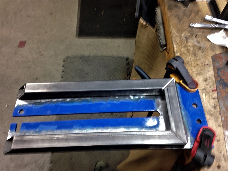
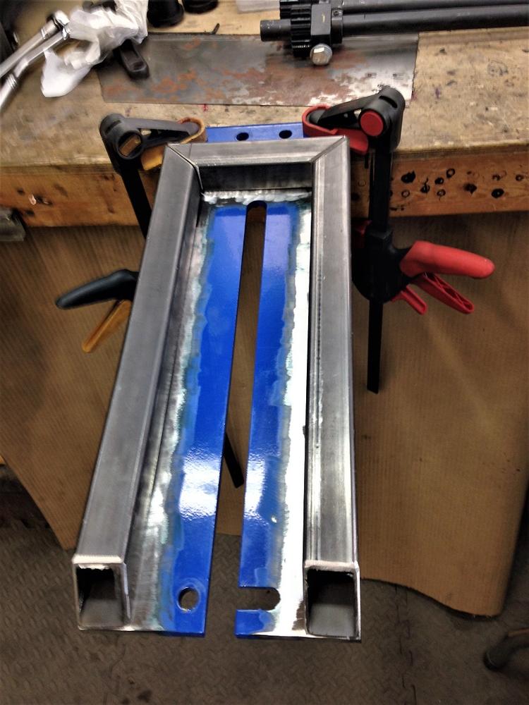
I welded the U tube and it suffered some distortion. It wouldn't lie totally flat and the open end narrowed 1/4''.
Now what, Dickstein? I scratched my head for a few minutes and decided to make a relief cut through three of the four tube walls. We clamped it down flat, welded it to the plate and welded the relief cut last...
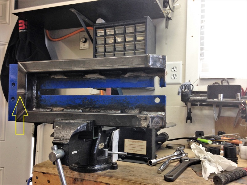
That worked as I'd hoped and we screwed the thing back together for a test push or six...
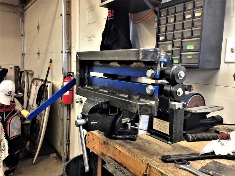
Mission accomplished. It doesn't twist and bend like the wet noodle it was out of the box. The dies stay centered on each other and it rolls 18 ga. easy. Now, we're itching for a few square yards of sheet metal. Maybe next weekend we'll have something to show for it...
.
With that in mind, B-tard bought one of those cheapie bead rollers and we stripped it down to make the necessary improvement...
We measured, cut and laid out some structural tube...
I welded the U tube and it suffered some distortion. It wouldn't lie totally flat and the open end narrowed 1/4''.
Now what, Dickstein? I scratched my head for a few minutes and decided to make a relief cut through three of the four tube walls. We clamped it down flat, welded it to the plate and welded the relief cut last...
That worked as I'd hoped and we screwed the thing back together for a test push or six...
Mission accomplished. It doesn't twist and bend like the wet noodle it was out of the box. The dies stay centered on each other and it rolls 18 ga. easy. Now, we're itching for a few square yards of sheet metal. Maybe next weekend we'll have something to show for it...
.
Attachments
Last edited:
Torchie
Well-known member
[cl [cl [cl [cl
[P [P
Torchie
[P [P
Torchie
Old Iron
Well-known member
[cl Dickstein [ddd[ddd[ddd
Those are pretty good little bead rollers, after the mod you guys made
Those are pretty good little bead rollers, after the mod you guys made
Skip
Well-known member
Looks good. I did something similar with my HF bead roller.

$209.99
$239.99
Solary Magnetic Induction Heater Tool - 1000W 110V Handheld Rusty Bolt Removal Tool with 8 Coils
solary

$229.99
$259.99
Solary Magnetic Induction Heater - 1000W 110V Handheld Bolt Removal Tool with 12 Coils
solary

$5.15
$40.00
Classic Car: The Definitive Visual History (DK Definitive Transport Guides)
Amazon.com

$23.99
$40.00
Classic Car: The Definitive Visual History (DK Definitive Visual Histories)
Amazon.com

$18.86
Green Stuff World for Models and Miniatures Set of Resin Giant Rats 3509 (GSWD-3509)
Cobb Co. Tech & Hobby

$36.00
BTMLTAI Rat Fink Joint Movable Car Culture Model Kit - Dark Green Retro Rat Rod Toy for Custom Car Enthusiasts
shenzhenMLTprintingCo.,ltd
DozerII
Well-known member
Looks great Doc, now you just have to replace the crank with and old steering wheel.
smallfoot
He's rockin' the "Nuttin Special"!
Looks great Doc, now you just have to replace the crank with and old steering wheel.
That would be another simple improvement that makes a world of difference.
Skip
Well-known member
A step in the right direction, but it still takes two people to operate the dang thing. Thus the reason that mind just collects dust. I am thinking of adapting the wheel from my HF tubing bender.Looks great Doc, now you just have to replace the crank with and old steering wheel.
Hoping for some great minds to chime in on this.
smallfoot
He's rockin' the "Nuttin Special"!
Two people sure makes it easier but just a round wheel will put you close enough to do small runs. Working with large pieces I have to call a buddy in. Motorizing them makes good sense if you use them a lot. Mine mostly collects dust... and motorizing mine puts more junk in my way.
Skip
Well-known member
I remember a discussion on motorizing these critters from ancient times, but couldn't find it in the first 15 pages. I have a suitable wheel or three around the shop, so I will try that first.Two people sure makes it easier but just a round wheel will put you close enough to do small runs. Working with large pieces I have to call a buddy in. Motorizing them makes good sense if you use them a lot. Mine mostly collects dust...and motorizing mine puts more junk in my way.
And my sincere apologies to the good Doctor for jacking his most interesting thread.
Dr Crankenstein
Rocket Surgeon
And my sincere apologies to the good Doctor for jacking his most interesting thread.
No problem, Skip. We can kick bead rollers around for a while!
Clearly, we're not breaking any new ground... just following good examples from smart, crafty persons who've done this before.
Now, we have a tool that works quite well, the gears naturally turn and thoughts of further modifications run the gamut. Dickstein
.
Skip
Well-known member
Cool. I wana see that.No problem, Skip. We can kick bead rollers around for a while!
Clearly, we're not breaking any new ground... just following good examples from smart, crafty persons who've done this before.
Now, we have a tool that works quite well, the gears naturally turn and thoughts of further modifications run the gamut. Dicksteinthinks he can devise something hands free and 100% mechanical, foot driven with a pedal or treadle or something... [S
.
DozerII
Well-known member
Old Iron
Well-known member
The motorized version is definitely an upgrade and a breeze for one person to operate the equipment.
I purchased this Baileigh 36" throat bead roller several years ago and have been pleased with it.
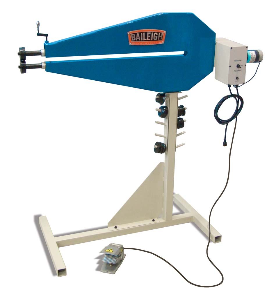
I purchased this Baileigh 36" throat bead roller several years ago and have been pleased with it.

Torchie
Well-known member
I have heard good things about the Baileigh as well OI.
I have seen pics of people that have built tables around them to support the sheet metal so that it is even easier for one person to feed the metal and operate.
Torchie
I have seen pics of people that have built tables around them to support the sheet metal so that it is even easier for one person to feed the metal and operate.
Torchie
Old Iron
Well-known member
I have heard good things about the Baileigh as well OI.
I have seen pics of people that have built tables around them to support the sheet metal so that it is even easier for one person to feed the metal and operate.
Torchie
That's the first thing I done was build a work shelf.
Dr Crankenstein
Rocket Surgeon
We played with the bead roller today. We started with a small piece (license plate size: 6" x 12") and quickly realized a couple of issues...
- Issue one: Tiny tight radius corners are difficult and create some gouges when you force the turn.
- Issue two: Patterns should be laid out in the correct orientation... if not, you get a reversed "print". (Oops!)
This is the back side of the small piece...looks OK, but the raised bead is on the other side, along with the die gouges and reverse image.
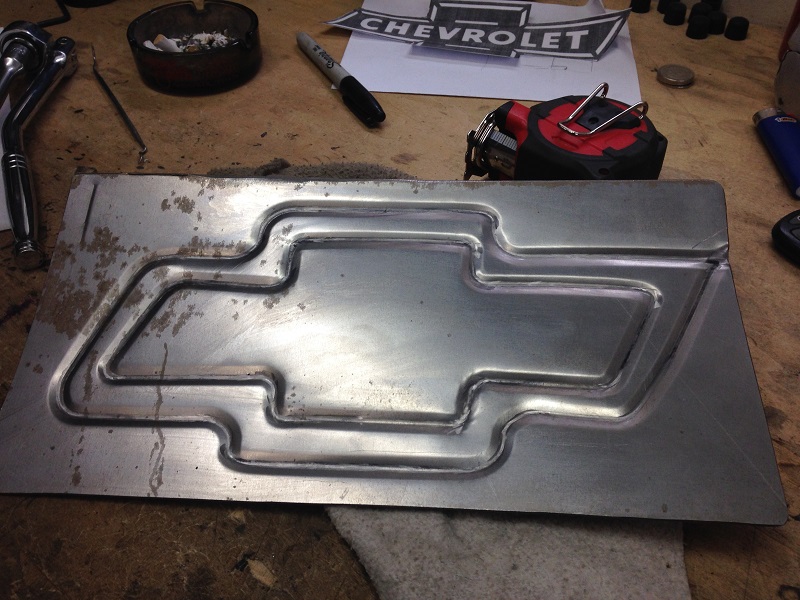
Back-tracking a little... I figured if we could work a small, tight piece fairly well, a larger piece should be easier... so, we tripled the size, drew the pattern in reverse and enlarged the corner radius to make it more manageable and avoid the gouges...
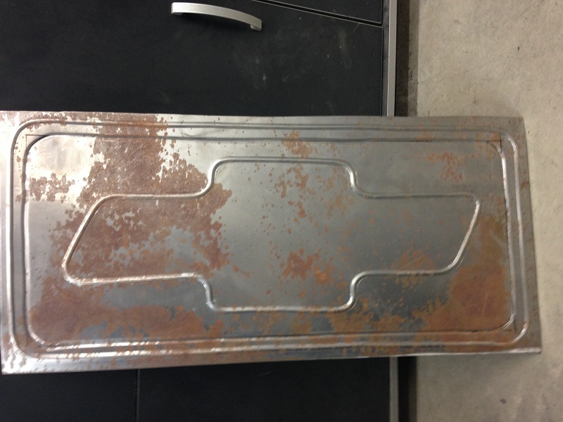
Not too terribly bad for a pair of professional idiots. We missed the mark here and there, made some crooked straight lines and the result is a bowtie somewhat resembling a baked cookie. (Practice is clearly required to create a work of art, but we're not concerned with art at this point.)
We turned our attention back to the car and the floor pans. As I mentioned previously, we found a couple well-disguised patches. As you might expect, the patches hid and probably contributed to a larger issue than they were meant to "repair".
We removed the tar-like slather and fiberglass... found a fairly small hole surrounded by perforated thin metal you could use to wrap a potato. We peeled it back to something solid and we now have a hole you could throw a cat through...
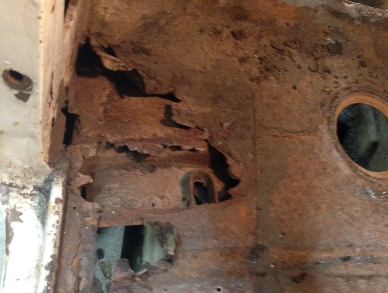
The hole (whole) section of the pan will be removed and replaced. The other side is different but similar. The bead roller should serve this repair well.
One last note: The pan is surprisingly complex. It's far from flat and has a depressed "well" of sorts, right where it's rotted away. We're convinced this is the source of the problem as the section has clearly rusted from the inside out...
.
- Issue one: Tiny tight radius corners are difficult and create some gouges when you force the turn.
- Issue two: Patterns should be laid out in the correct orientation... if not, you get a reversed "print". (Oops!)
This is the back side of the small piece...looks OK, but the raised bead is on the other side, along with the die gouges and reverse image.
Back-tracking a little... I figured if we could work a small, tight piece fairly well, a larger piece should be easier... so, we tripled the size, drew the pattern in reverse and enlarged the corner radius to make it more manageable and avoid the gouges...
Not too terribly bad for a pair of professional idiots. We missed the mark here and there, made some crooked straight lines and the result is a bowtie somewhat resembling a baked cookie.
We turned our attention back to the car and the floor pans. As I mentioned previously, we found a couple well-disguised patches. As you might expect, the patches hid and probably contributed to a larger issue than they were meant to "repair".
We removed the tar-like slather and fiberglass... found a fairly small hole surrounded by perforated thin metal you could use to wrap a potato. We peeled it back to something solid and we now have a hole you could throw a cat through...
The hole (whole) section of the pan will be removed and replaced. The other side is different but similar. The bead roller should serve this repair well.
One last note: The pan is surprisingly complex. It's far from flat and has a depressed "well" of sorts, right where it's rotted away. We're convinced this is the source of the problem as the section has clearly rusted from the inside out...
.
Attachments
Old Iron
Well-known member
That was a good result on a first time run.
On tight corners, they have what is called Artisan dies to do artsy stuff.
On tight corners, they have what is called Artisan dies to do artsy stuff.


