My 1941 Dodge Truck Build

Rat Rods Rule

Help Support Rat Rods Rule:

This site may earn a commission from merchant affiliate links, including eBay, Amazon, and others.
The frame is looking great!

Does the distance of the links from the center line affect the "Tippiness" or is it just the spring/airbag distance from the center line? (I probably misunderstood the whole tippiness thing.) Anyhow, it looks better with the links inside the frame.
 
Gonna knock 'em out at the Main St.cruise!
59874214644fcb4610ad62-1.gif
 
The frame is looking great!

Does the distance of the links from the center line affect the "Tippiness" or is it just the spring/airbag distance from the center line? (I probably misunderstood the whole tippiness thing.) Anyhow, it looks better with the links inside the frame.

I think the location of the actual links dictates how much stress due to axial loading (tension/compression) is on the link. For instance, if you place a link only 5" away the centerline of the rearend, it'll experience a lot more stress than a link that is placed 20" away from the centerline. More stress means more flex (within the rear axle and suspension links) and therefore a "less accurate" suspension setup. It probably won't be very noticable on a street car, but on more "serious" cars, suspension geometry is key.

The placement of shocks and springs dictates the suspension response. I took 2 semester of systems, controls and vibrations in college, and although I want to forget about those classes, it always comes back to bite me in the ass, LOL.

Gonna knock 'em out at the Main St.cruise!
59874214644fcb4610ad62-1.gif

:cool:
59874214644fcb4610ad62-1.gif


I love the frame , very industrial looking , that's a lot of nice welding !

Thank you so much! It was a lot of welding, A LOT! Haha

-------

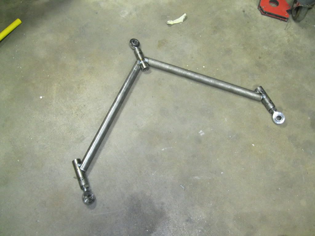
I made some more progress tonight. I got the upper link of the rear suspension built and tacked. I used a very high tech method of fabrication that I will be patenting, LOL, just kidding! Sorry if this stuff sounds boring. I figured a detailed explanation of the process with pictures might help some people overcome the "fear" of getting into a project like this.

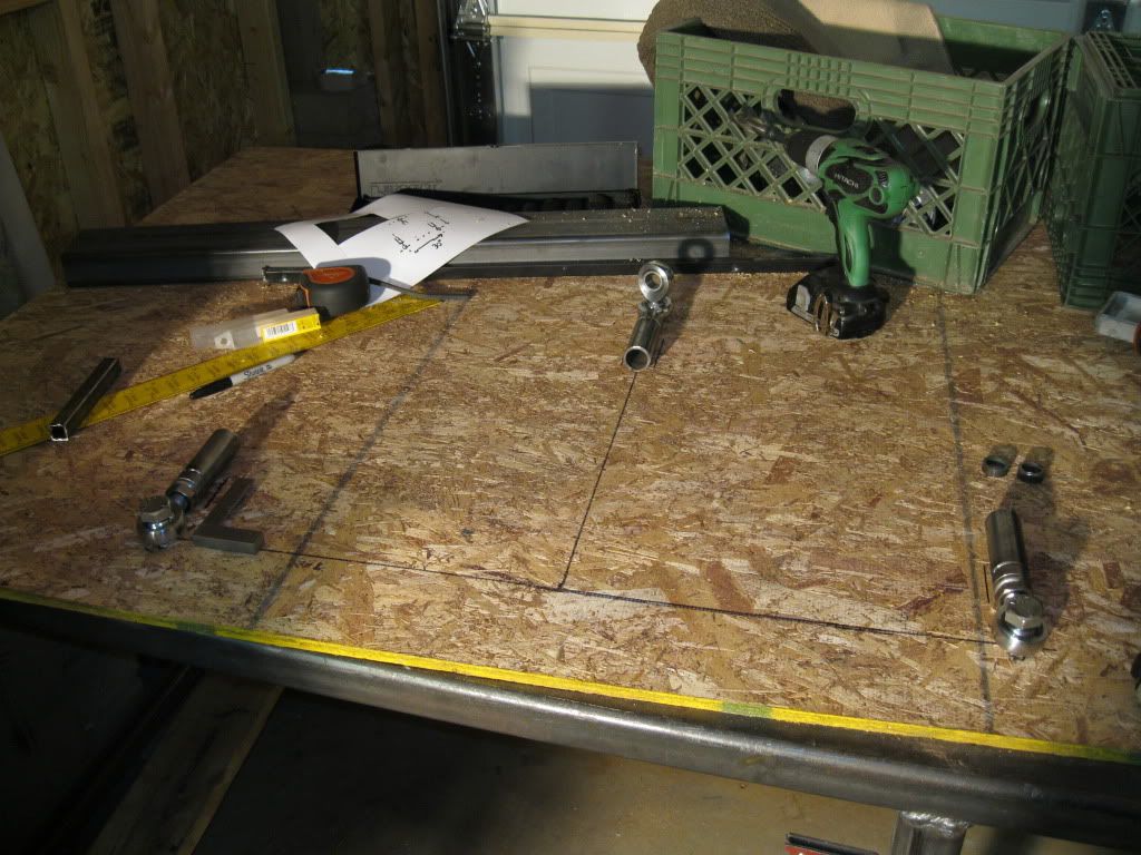
Anyways, I drew out the upper link geometry on a piece of board and positioned the heim joints in place.
IMG_0122.jpg


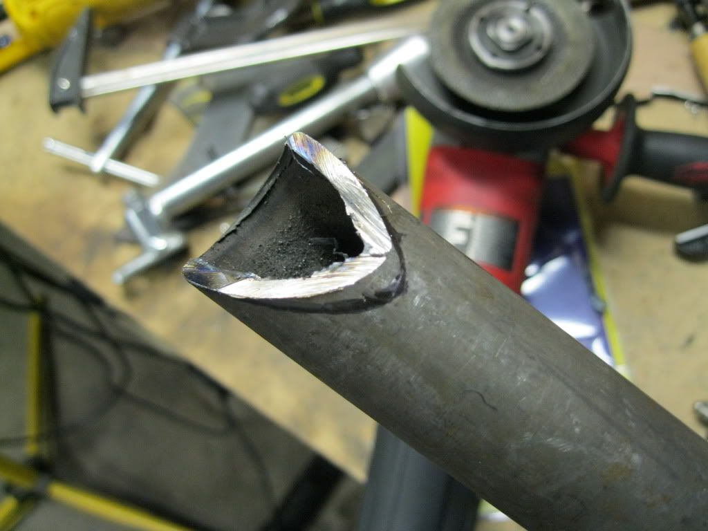
I generated some tube notching templates using The Metal Geek program and notched my tubes using a grinder.
IMG_0127.jpg


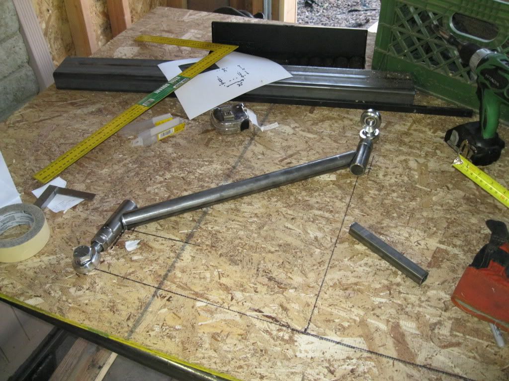
I cleaned up the rough cut with a flap disk, but my camera ran out of battery and I don't have a picture of that. I did a quick test fit on the template to see how everything lined up.
IMG_0123.jpg


I cut and notched another tube like the one above, test fitted and tacked.
IMG_0129.jpg


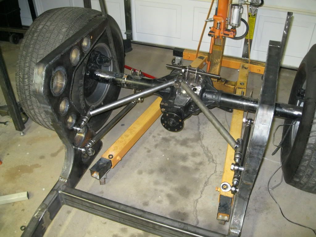
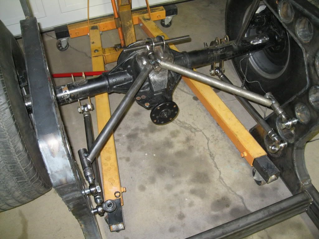
Here's a test fit on the frame. The rear axle isn't centered on the frame and I was too tired to get it centered. I also haven't made all the correct spacers yet, but it looks like it's going to work!

IMG_0132.jpg


IMG_0130.jpg


Thanks for looking! :)
 
detail is awesome! If you are here and reading stuff like this then the detail is what you want. Looks good! [;)
 
Thanks for the suspension explanation.

Interesting upper link design. Is that 1" OD 1/8 wall? Is there a sway bar going on? I'll be interested to see the airbag and shock mounts. Could you work a little faster - I'm having trouble waiting for the next chapter. :D

By the way, if you decide to paint the frame - you're welcome to borrow my rotisserie. Won't be needing it until the next project.
 
Very interesting design, hope you plan on gussetting those corners. There will be a lot of stress on the angles near the frame on the upper arm.
 
Your 3 link looks pretty good - probably the biggest stress point would be the front 4 bolts thru the heim joints into the frame. What you have in this configuration is called single shear mounting - if you add another plate/bracket on the other side of each joint under the bolt heads, then you have double shear mounting - double the strength and the mount bolts are totally stable then, actually the same as you have on the rearend brackets.
Just my 2 cents worth...
 
detail is awesome! If you are here and reading stuff like this then the detail is what you want. Looks good! [;)

Thanks bud! :)

Thanks for the suspension explanation.

Interesting upper link design. Is that 1" OD 1/8 wall? Is there a sway bar going on? I'll be interested to see the airbag and shock mounts. Could you work a little faster - I'm having trouble waiting for the next chapter. :D

By the way, if you decide to paint the frame - you're welcome to borrow my rotisserie. Won't be needing it until the next project.

Thanks! The upper link design is actually a lot more common than you might imagine.

The tubing is 1.25" O.D. 0.120" wall thickness DOM. I have thought about adding a sway bar, but it's not designed in the CAD. It's one of those things where I'm going to wait until the end to see how I'm going to approach it.

I'm having trouble waiting for the next chapter, too! :D :D

Thank you so much for the offer on the rotisserie. It's very nice and generous of you. I'll keep that in my for when the time comes, but I think if I add even another screw driver to this garage, it'll blow up! Haha!

Thanks again! :)

Very interesting design, hope you plan on gussetting those corners. There will be a lot of stress on the angles near the frame on the upper arm.

Thanks for your suggestion! :) I agree with you that a gusset is probably a wise thing to add. I will be adding a dimpled sheet metal gusset across the two angled tubes. It would look better than a regular flat plate gusset and would add plenty of strength.

Your 3 link looks pretty good - probably the biggest stress point would be the front 4 bolts thru the heim joints into the frame. What you have in this configuration is called single shear mounting - if you add another plate/bracket on the other side of each joint under the bolt heads, then you have double shear mounting - double the strength and the mount bolts are totally stable then, actually the same as you have on the rearend brackets.
Just my 2 cents worth...

You are absolutely right; the biggest stress points are where the 3-link attaches to the frame.

As far as double shear vs. single shear goes, I don't know if you can quantify it as "twice as strong", but following your logic, it'll probably more than twice as strong. Not only are you distributing the load across a bearing area that is now twice as large, you're also eliminating the stress due to bending at the bolt. This of course is only true if the bracket is rigid.

In my case, I'm using 3/4"-16 grade 8 bolts, so I'll be fine! :)

---------

There's nothing interesting to report tonight. I got all my hardware from McMaster, did some welding on the upper link and picked up a Ford Explorer driveshaft from Craigslist for $40. I just need to get a slip yoke for my TH400 and a weld on 1310 yoke and I'll be set! :D

Thanks for looking! :)
 
If it's not too late to change it, think about rotating the rod end on the axle end of the wishbone 90° so the bolt is vertical.
All the side load at that end of the car runs through that single joint and the ball tends to end up pushing the linings out of the joint.

If it's too late to change it just keep an eye on it once it's running.

Even having the bolts at the chassis end of the wishbone horizontal isn't ideal, but the load at that end is shared across both joints, so they tend to cope OK usually.

3/4" in single shear should be OK I'd think, you could calculate the torque your tyres are able to generate vs the bending load your bolts can handle before yield if you are worried about it. Dan Barcroft's 4-bar calculator has all that in it and is a free download.

Chassis looks slick by the way :D

Thanks!

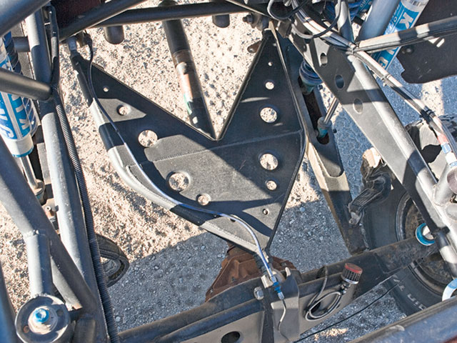
Great point about the ball popping out of the heim joint. It didn't even occur to me that the ball could pop out. It's definitely a valid and possible mode of failure; I just don't know how much stress it would take for these heims to fail in the manner that you mentioned. A lot of high horse power off road race trucks (like the pre runners and trophy trucks that run the Baja 1000) run a very similar suspension design, with the heim joints oriented in the same manner as my setup. Here's a picture for reference:

chadleising-8.jpg


I'll crunch some numbers tonight. My intuition says I have a big factor of safety with this design, but now I really want to see some numbers. :D

BTW I don't mean to criticize I like the design, just not that familiar with it.

Criticism is great, I don't mind it at all. As a matter of fact, I welcome it. For instance, wendle brought up a great point about the balls popping out of the heim joints under great stress. I had not even though about that.

I appreciate the feedback, ideas, opinions, criticism and the time you guys take to reply! :)
 
I've seen those trucks run and it is safe to say they take a pounding! That is also a sexy suspension setup! [dr
 
I've seen those trucks run and it is safe to say they take a pounding! That is also a sexy suspension setup! [dr

Yes! I think as long I stay on the street and off the dunes, nothing in my suspension is likely to fail! :D LOL

----------

I didn't do anything exciting tonight. I started working on the front "wishbones" and bat wings.

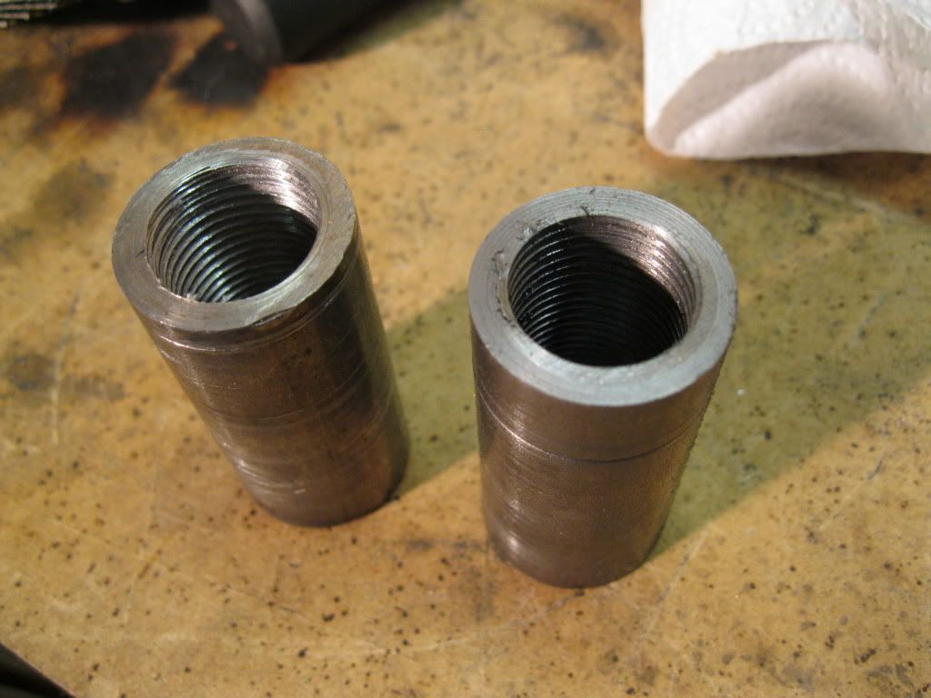
I had a coworker of mine make these bosses for me today. They are 1" solid round stock that are drilled and tapped to 3/4"-16. Each one is 2" long. He did 6 of them. He didn't know what he was getting himself into. It's tough really tapping a hole that big by hand. I'll have to buy him lunch tomorrow.

IMG_0136.jpg


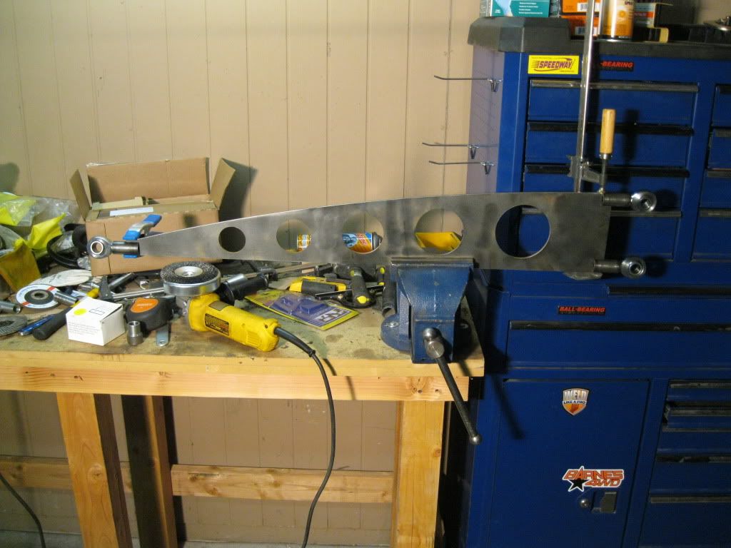
I got the heim joints in the bosses and put them on the radius rod to see how everything lined up. I have to buy 2" flat stock tomorrow to add the top and bottom rails (essentially making it an I-beam). I can then put it on the car.
IMG_0135.jpg


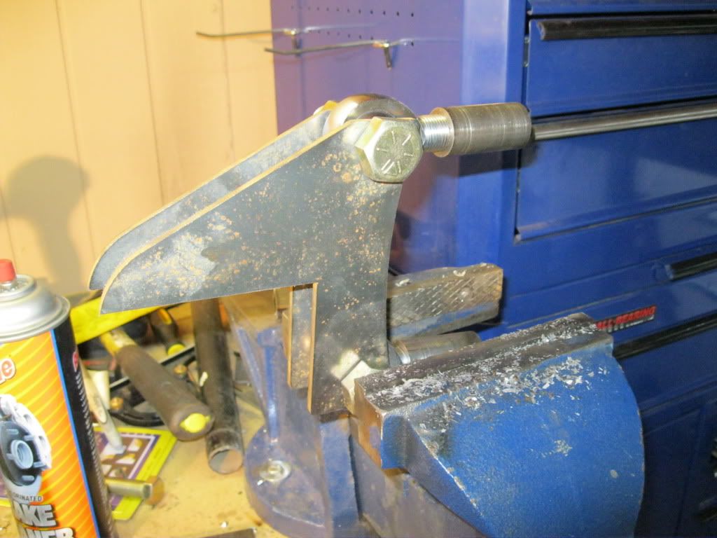
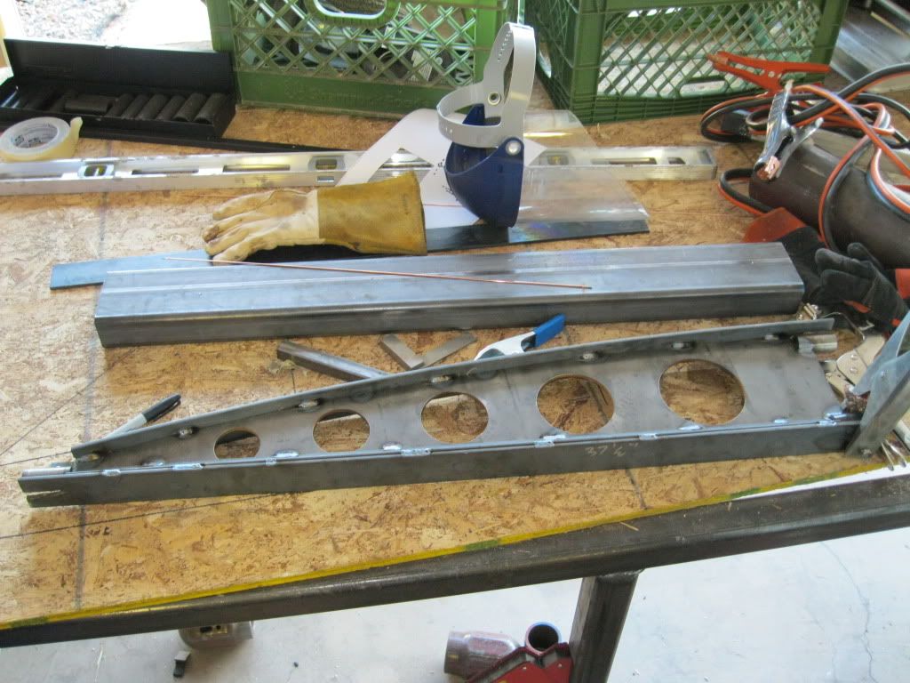
I also made one of the bat wings. I may not end up keeping these. I have to see how I end up feeling about them in a few days. LOL
IMG_0137.jpg

IMG_0142.jpg


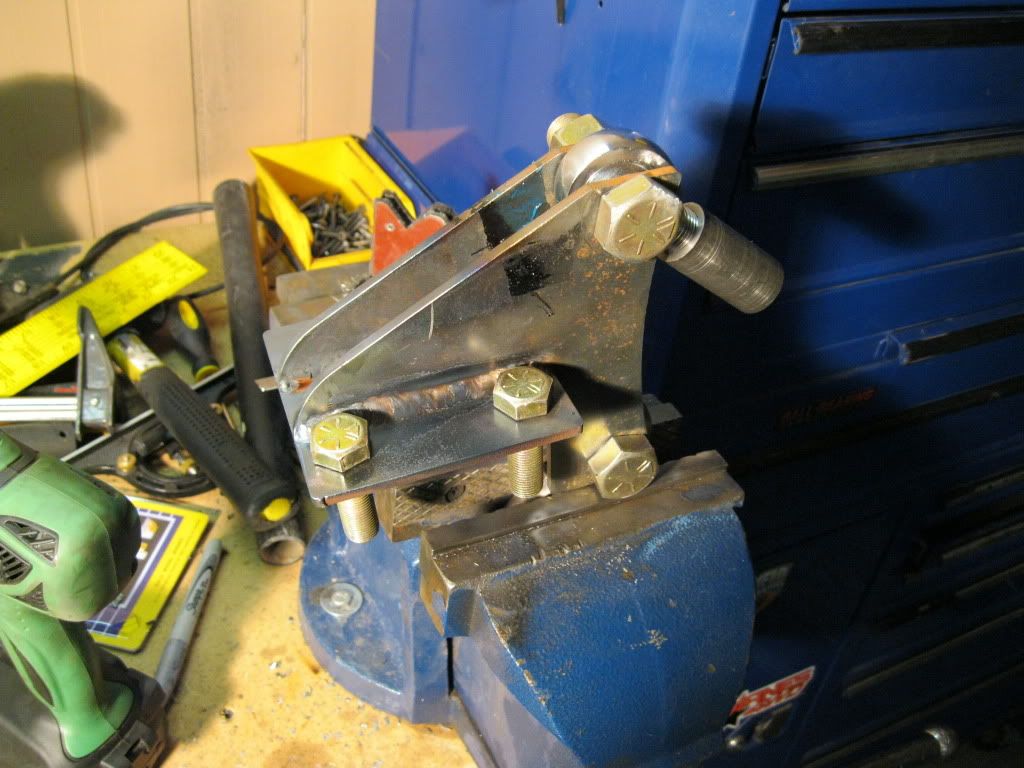
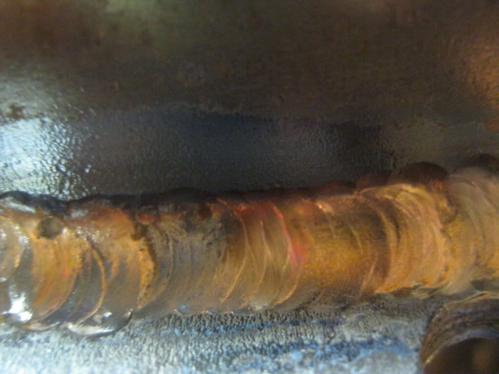
I also tried to practice "walking the cup" when I TIG welded the bat wings. It's a really difficult technique, and I suck at it! I could only do a few beads that actually looked decent, right in the middle of the picture. From my understanding, it involves revolving the torch in an 8-figure as well as moving it forward. It's pretty freaking difficult and I think the horrible looking weld shows. It was the second pass, so the part is plenty strong.
IMG_0140.jpg


Thanks for looking! :)
 
Your radius rods are going to be yet another trick and unique part, lookin' good. What front axle are you using - oh, right! - the Dodge, I like dip in it. Have you considered drilling it to use a conventional single perch bolt like Fords? I did that with mine and on another Chev axle to get rid of the clunky bolt on batwing, it really cleans up the look.
 
The front axle is actually off of a 1955 Ford F100. I think I may be crazy, but I kind of like these big bulky axles, LOL.

I hope the radius rods turn out good. I want to get this thing rolling soon. :)
 
How about milling a slot in one side of a 1" tube and slide that over the top and bottom of your front wishbone? [;)
 
How about milling a slot in one side of a 1" tube and slide that over the top and bottom of your front wishbone? [;)

I thought about that actually. The only problem is I have no way of milling a slot, especially that long, in a piece of steel tubing. :( :(
 
A little update:

I worked on the radius rods over the weekend. I managed to get them all tacked up. I just need to finish welding them.

IMG_0150.jpg


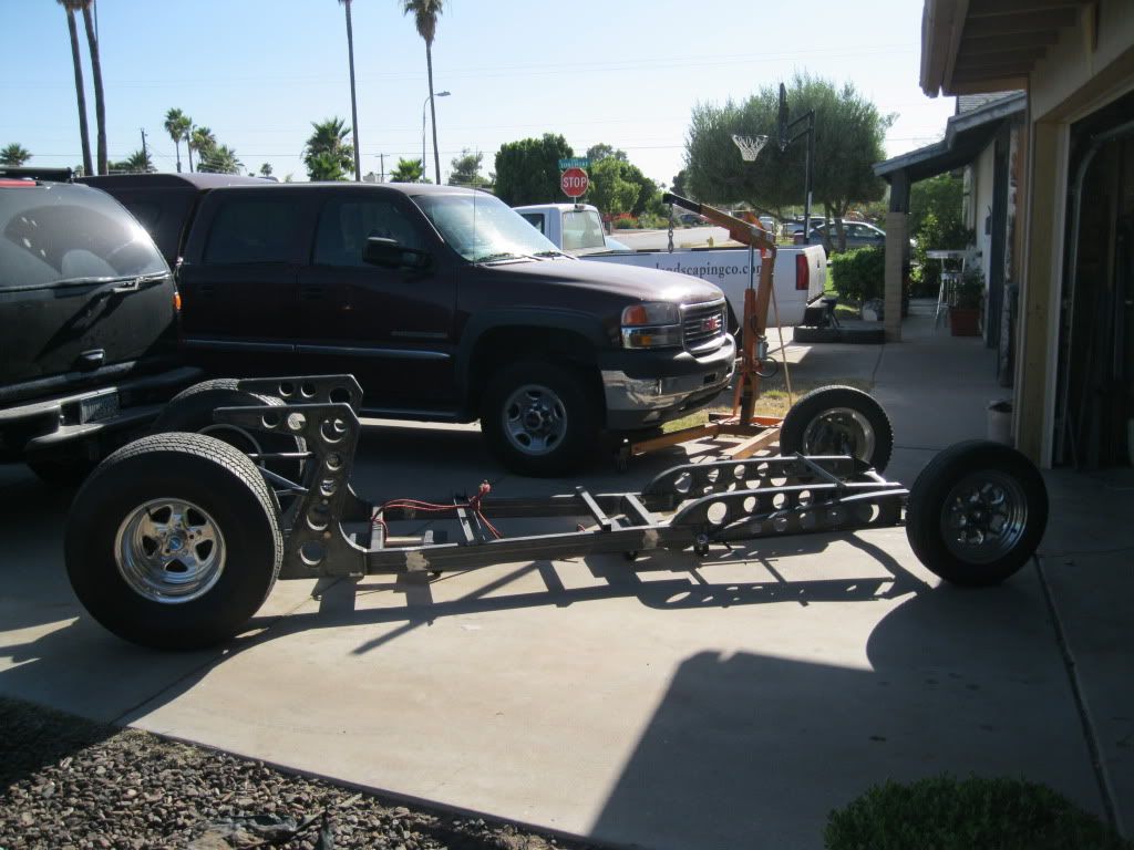
I put them on the front axle and rolled the frame outside. It looks pretty long, but I like it! :D
IMG_0147.jpg


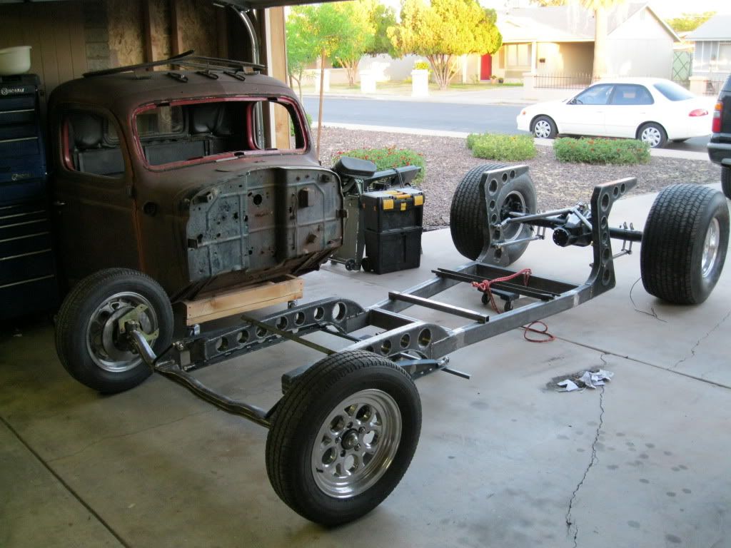
I brought the cab in, sat across the garage and looked at it for a solid 30 minutes while listening to Bob Marley and drinking Coke, LOL. I need to figure out what I want to do with the paint. I wanted to leave it weathered like it is now, but it's not great looking patina. How would bare metal look?
IMG_0154.jpg


I still need to trim the radius rods so they move around the frame with a reasonable amountof clearance. I also need to buy a 1" drill bit tomorrow to drill the frame for the radius rod bosses. Good times! LOL :rolleyes: :cool:

Thanks for looking! :)
 

Latest posts

Back
Top