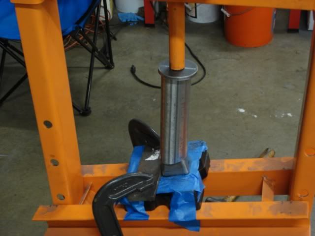
That was only the beginning of the reshaping process. Next Dan had to move to the bench and slip the tube over a piece of 1.5 x 1.5 box tubing that was clamped to the bench and he used a body hammer to further reshape the rectangular end so it fit snuggly into the flange. It sounds easy but he would have to shape it a little, then try it, then reshape some more and try it again. After a while the tube would finally fit well enough and then we could move on to the other end of that tube so it would slip into the cone .
We found out there are a few ways to weld each tube to the cone. One way is to punch a hole the same size as the tube, slip the tube slightly into the cone, and then weld around each tube to secure it to the tube. The second way is to "cope" the end of each tube so that it really doesn't enter the cone, but just sits flush against the outside and then you weld all around the perimeter of it (after you cut a hole in the cone so exhaust can get through).
We looked up inside the Sanderson Limefire headers I have on my 27 and we saw that they cut the hole and slid each tube through the cone then welded it up. That is what we decided to do on this new set. But to complicate things, the hole does NOT end up being round, like the tube. It gets back to the angles we were talking about earlier. The cones are not sqaure to the engine, they are angled out and pointed down, so the holes end up being an oval shape instead. This took a lot of time because Dan first had to figure out exactly where each tube would enter the cone, then first cut a round hole, and then keep grinding a little at a time until the oval shape was just perfect so the tube would slip in and not bind.
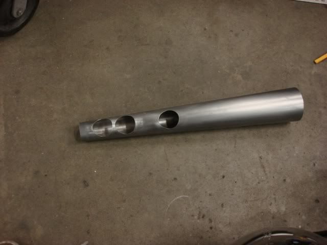
We were going to use a holesaw for the initial cuts on each hole but we were afraid it would grab and bend up the cone. So Dan marked the area to be cut out and then drilled four little holes around the perimeter of it and then used an air saw to cut each hole. Then he used a drum sanding disc on a die grinder to oval out the hole to the right shape. Here is the cone after all that was done.
Those 3 holes are for the number 2 -3-and 4 tubes to fit into. Number one goes into the small end of the cone.
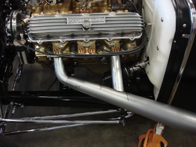
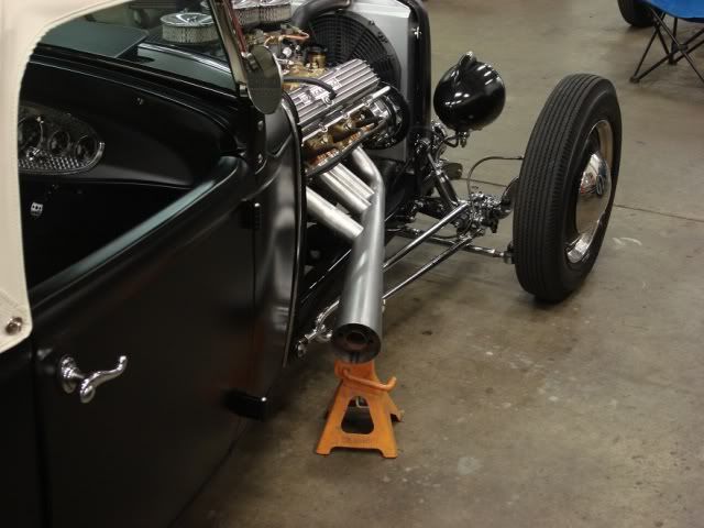
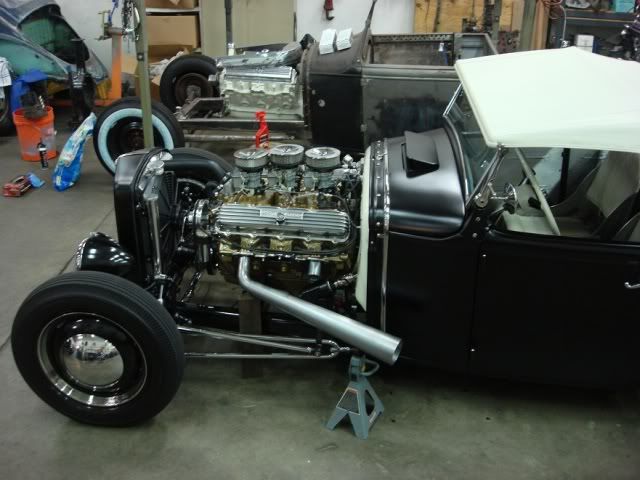
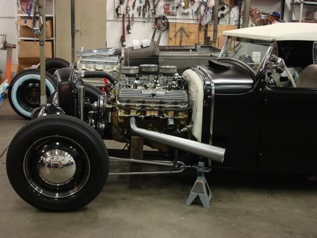
Once we had the number one curved tube cut and the number 4 straight tube cut we loosely assembled the header to see how it would look and if we liked it that way. Here is what that looked like.
You will notice that in the picture above only the number 1 and 4 holes are present. It is impossible to cut all four holes at one time because you have no way of knowing where they will actually end up, so it is best to cut one hole at a time and make that tube fit well before you move onto the next tube. The picture I posted of the cone with all the holes cut was the end result after fitting each of the tubes.
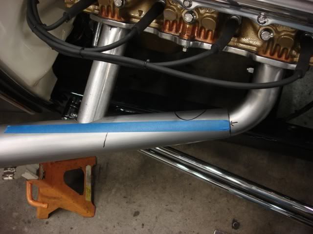
To get the tubes to enter on the same plane takes some doing. We ran blue masking tape in a straight line to give us a reference mark so we could cut the number 2 and 3 holes at the same level. The odd shape of the cone makes it really tough to know where a straight line is, so it took us some figuring and time to get it right.
I could not type enough words to explain how much work it took for Dan to be able to scribe that mark on the cone for the number 2 hole. He made a dummy tube that was coped so it would lay on the outside of the cone and that was a perfectly straight shot to the exhaust port on the flange. It entailed lots of measuring ,some paint sticks cut to shape as a guide, and some guessing. It just takes a lot of calculating because once the holes are cut it it too late to turn back.
I have to stress here that NOTHING will be welded until all the tubes are cut and fitted perfectly. We literally had these together and apart 100 times, making little adjustments in the fit until we had it where we liked it.

")